Computing and Maintaining Transforms and Volumes in Scene Graphs
Scene graphs are a basic concept of computer graphics. The computation of bounding volumes and transformations within a tree-like hierarchy is a basic, re-occuring task for people working in 3D graphics development. However, when things get a bit more complicated and optimizations come into play, bugs can occur quite quickly - even if you have some experience with the topic. In fact, I would guess that, when writing a 3D engine from scratch, optimized maintenance of transformation hierarchies during runtime is probably one of the parts of the code that will likely cause one or another bug during early development. Therefore, I found it helpful (for myself, and hopefully also for others) to summarize again the most important aspects by example within this little article. So, let's get started!
A Basic CAD Example
Throughout this article, we will use a small CAD application as example. Let's assume we want to visualize a CAD model, which has an assembly tree that organizes parts hierarchically. Click the following image to see a small demo.

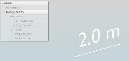
To avoid making things unnecessarily complicated, we will assume that the hierarchy within our scene graph is actually a tree, which means that nodes are not allowed to have multiple parents. Having a tree hierarchy is also a very common case for CAD scenarios. You can see the example scene's hierarchy in the small overlay on the upper left side of the page (see also Figure 1).
As you might have noticed from the demo, there are basically two top-level elements, entitled FOUNDATION and BLOCK_ELEMENTS. The first one is simply the dark gray plate. The second one is actually a group, holding the two red objects (RIGHT_BLOCK and LEFT_BLOCK). In addition to that, to make things more interesting, the group also holds an element which is not visible within the scene hierarchy. This element is a 3D annotation, showing a measurement. Such elements are sometimes associated to CAD data, as part of the so-called Product and Manufacturing Information (PMI). As can be seen from the demo and from Figure 1, this makes things more interesting, since geometry can potentially be attached to all the nodes in the scene graph, not just the leaves.

Transforms and Volumes: From Local Data to World Space
Having an example at hand, let's get started with the actual topic: transforms and volumes! First, let's clarify the meaning of both terms, according to how they are used within this article.
A Volume, corresponding to a node within the scene graph, is usually represented as a simple bounding geometry, such as a bounding box or a bounding sphere. For a Local Volume, these bounds are computed from the untransformed geometry of the corresponding node (i.e., in Object Space). In contrast, a World Volume contains a transformed version of the local volume. It is computed by taking into account the position, scale and orientation of the node within the 3D scene. Moreover, the world volume holds the accumulated volumes of the node's children. Inside a CAD application, we can use this volume to fit the 3D view to the content of a certain subgraph, for example.
A Transform determines the position, scale and orientation of an object or subgraph within the 3D scene. We will define the transformation introduced by a certain node within the scene graph as the node's Local Transform. When the local transform is applied hierarchically within the scene graph, we can compute, at each node, the resulting World Transform of the node's geometry. It will be used by the rendering system to position, scale and orient the object correctly inside the visualized 3D world. It seems to be a common open question whether the local transform introduced by a node should also be applied to the geometry of the node itself, or only to the node's children. Here, we assume that the local transform always also affects the geometry of the node itself.

Typically, the data which is changed by the user, or given by a tool that exports the 3D scene, is the local data. Within the X3D standard, for example, we can only define local transformations and local volumes. Likewise, an API will probably only allow the user to change the local transform. This allows, for example, to make a part rotate, to translate parts, scale them, and so on. The local volume can be changed indirectly by the user, by exchanging the geometry of a certain node.
In contrast to this two kinds of local data per node, which we assume to be the original source of information, the world volume and world transform are usually only stored for runtime optimization. Assume, for example, we would want to fit our 3D view to a certain group of parts, which is represented by a node within the scene graph. Then we would start to traverse the scene graph, top-down, following the path from the root node to the group node, in order to compute the world transforms for the group node, and for all of its child nodes. Having computed all the world transforms, we could then traverse the scene graph bottom-up, until we reach our group node, to compute its world volume. Finally, we would fit our view to that volume. As can be guessed from this example, always computing world transforms and world volumes when they are needed can become pretty inefficient, in terms of computation time. This aspect becomes crucial if a scene contains not just a few, but instead thousands of nodes. Therefore, a necessary optimization is to compute the world transforms and world volumes only once at application startup, for all nodes, and update them only if a local transform or local volume gets changed somewhere inside the graph.
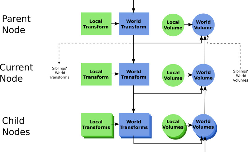
Figure 2 illustrates the dependencies between the four properties that we can store for each node within a scene graph, Local Transform, Local Volume, World Transform and World Volume. The world transform at each node is affected by the local transfom, which gets combined with the world transform of the parent node. The world volume at each node depends on the (accumulated) world volumes of the child nodes, plus the local volume of the node (if any), transformed to world space. It can also be seen from the flow of dependencies that change of the local transform basically triggers a re-computation of all children's transformations, and of all parent's volumes. Changing the local volume of a node (for example, because the attached geometry was exchanged) results in a re-computation of the world volumes of that node, and of all its parents. The following pseudo code also illustrates these dependencies.
Updating World Transforms & Volumes:
class Node {

...
// PUBLIC API
function setLocalVolume(volume) {
    this.localVolume = volume;

    //update world volume for this node
    this._updateWorldVolume();

    //propagate change of world volume to parents
    this._updateParentWorldVolumes();
}

function setLocalTransform(transform) {
    this.localTransform = transform;

    //update world transforms and world volumes for this subtree
    this._updateSubtree();

    //propagate change of world volume to parents
    this._updateParentWorldVolumes();
}

// PRIVATE FUNCTIONS
function _updateWorldVolume() {
    this.worldVolume = this.localVolume.transformBy(this.worldTransform);
    for (child in this.children)
        this.worldVolume.extendBy(child.worldVolume);
}

function _updateParentWorldVolumes() {
    this.parent._updateWorldVolume();
    this.parent._updateParentWorldVolumes();
}

function _updateSubtree() {
    this.worldTransform = this.localTransform * this.parent.worldTransform;
    for (child in this.children)
        child._updateSubtree();
    this._updateWorldVolume();
}

}
Implementing these computations correctly can already become tricky. Especially, when traversing the tree recursively top-down in _updateSubtree, we should not call _updateWorldVolume recursively for all parents. Here, this is ensured by using two different functions for computing the world volume of the current node, and for updating it on the parent node. If we would have only one, recursive function instead, and use that inside _updateSubtree, we would end up updating the volume of inner nodes multiple times, as there would be a recursion upwards (to update the parent's volumes) inside another recursion downwards (to update the child transforms). This is obviously something we don't want, and it is important to pay attention to such small, seemingly detail aspects.
Using Precomputed World Transforms & World Volumes
Until now, we have assumed world transforms and world volumes to be computed only once (and to be updated if necessary), as a first runtime optimization. Let's see if we can even go one step further. Assume we would have a pretty complex scene, with thousands of nodes. In that case, we may want even to pre-compute the global transforms and global volumes offline, instead of having these computations being executed every time a user loads the scene. The most straightforward solution would probably be to set them directly as properties of the nodes, without using the public API functions.
One thing to keep in mind in this case is that we actually need (matching) local transforms and local volumes, if we want the user to be able to update transformations later on. Local transforms can be computed from given world transforms, using the inverse process of the computation of world transforms. However, since this process is time-consuming itself, there is no real sense in using pre-computed world transforms as an optimization, if the user should be able to manipulate transformations during runtime. Local volumes can be computed from world volumes, if only the leaf nodes contain geometry. If the inner nodes contain geometry, however, it is not possible to reconstruct their local volume from their world volume. This is because the global volume is computed using the accumulated world volumes of the child nodes, and since volumes may usually overlap, we cannot tell afterwards which part of the world volume contains the node's own geometry. For our small CAD example, for instance, we assumed that the 3D annotation, showing the measurement, is attached to the group BLOCK_ELEMENTS. If we would want to transform the annotation, and if we wouldn't have a local volume for it (stored with the BLOCK_ELEMENTS node), we could not tell how the transformed volume of the 3D annotation would look like. This would make it impossible to safely cull this object during rendering, for example. As can be seen, we should only use precomputed world transforms and precomputed world volumes if transformations are never changed during runtime, or if we really have all possible information at hand, including local volumes and local transforms.
And that's already it :-) I hope you could benefit a bit from this summary of the topic - if you have interesting thoughts to share, feel free to write me an email, or a comment on twitter.
Other Articles